From breadboard
to built.
Originator & sponsor. Utmost Connect works closely with academic institutions to sponsor applied engineering programs — originating each of these concepts, funding and directing their technical development, and building working prototypes alongside student engineering teams at UC Irvine's Mechanical & Aerospace Engineering senior-design program. These are prototypes in active development, not closed coursework: every project here has advanced to a funding pitch, and Home Lock took first place at its UCI design showcase.
Home Lock Management System
A clip-on sensor that tells you whether the door is actually locked.
TeamBEND-CL MechTechs — Criss Azer, Brady Muramoto, Edward Leija, Neil Hoffman, Lucas Lin, Daniel Stoll
Academic year2023–2024
Officialprojects.eng.uci.edu ↗
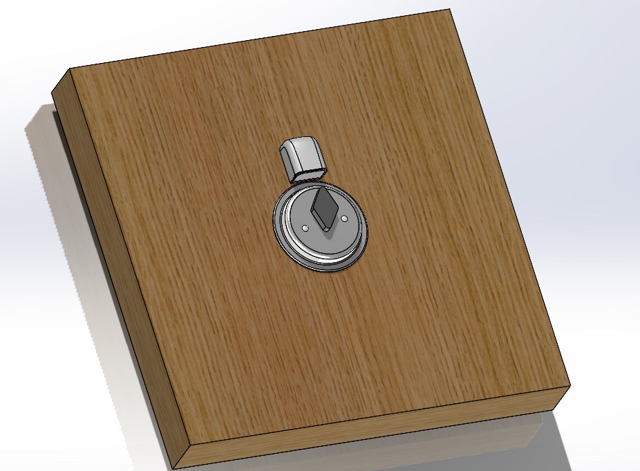
Most homes have no reliable answer to “is the door actually locked?” Commercial smart locks solve it by replacing the whole deadbolt — $100–350+, a visible aesthetic change, and no coverage for windows at all. My concept: a cheap, invisible add-on that reports lock state on doors and windows without touching the existing hardware — funded and technically directed through my company, built with the student team below.
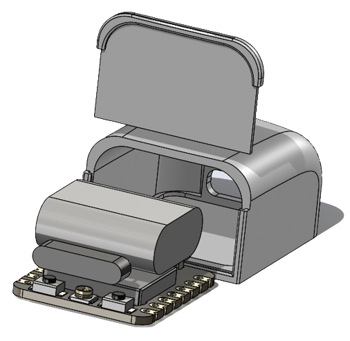
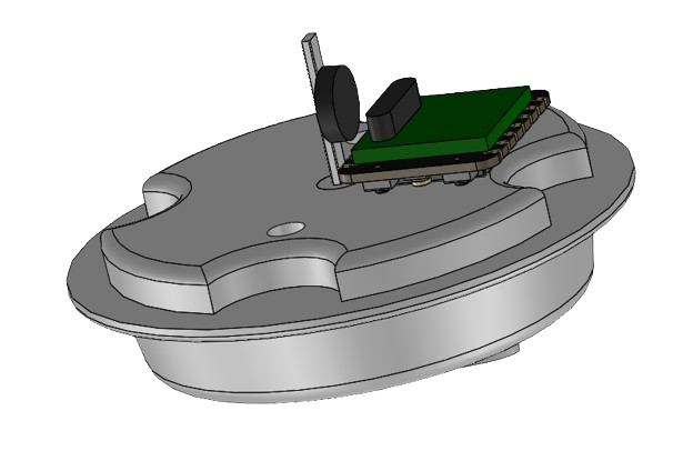
A small sensor clips onto the deadbolt's slide bolt (or a window's sash) and reads position with a reed switch and magnet — no rekeying, no visible hardware change. It reports locked or unlocked over Wi-Fi in real time to a phone.
- Electronics shrank across the project — from a full STM32 Nucleo dev board down to a coin-cell-sized ESP32-C3 for the final MVP.
- Firmware watches a reed switch on a pull-up pin and publishes a locked/unlocked event over MQTT the instant the state changes.
- A parallel reed-switch sensor was built for windows, extending the same approach to whole-entry monitoring — the gap the team's competitive teardown (August, SimpliSafe, Ring, Nest, and Saratech's own smart-sensor line) found no one else covered well.
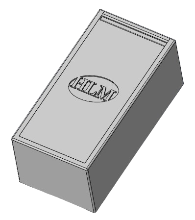
- Housing went through five SolidWorks revisions (V1–V5), refining battery compartment, hinge, and thumbturn clearance for a clean non-invasive retrofit.
- Door-to-phone latency verified live — a state change on the deadbolt reaches the app in about a second (Fig. 06; Clip 01 for the bench bring-up).
- Modeled at $13.93 per unit against $100–350 for commercial smart locks; per-unit material cost fell from $9 (V1) to $3 (V3) as the design matured across three prototype generations.
- Business case explored a B2B path — partnering with door manufacturers (e.g. Marvin Doors) to embed the sensor at the factory, rather than selling direct to consumers.
- Took first place at its UCI design showcase, then went on to a full investor pitch — the path from student prototype to funding conversation, not just a class deliverable.
- That path got real traction, not just a slide: Styline Windows & Doors reviewed the prototype in person and expressed interest in participating, alongside early conversations with an outside investor.


Autonomous Fire Extinguishing System
It finds the fire, aims, and puts itself out — no one has to pull a trigger.
TeamTeam 3, “Fire Fight Club” — Matthew Keith, Christopher Tran, Yuqi Hu, Chris Rami Makarem, Benson Yu
Academic year2024–2025
Officialprojects.eng.uci.edu ↗
A small fire can outrun a person's reaction time. I framed the alternative directly against traditional sprinkler systems — pricey, slow-responding, and hard to install — and directed the team to build a ceiling-mounted system that finds a fire's exact location on its own, aims at it, and suppresses it within 10 seconds of detection (an early pitch-deck target had been 30s), built against NFPA 750 (water-mist fire suppression).
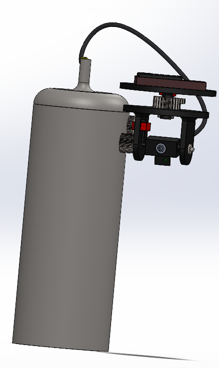
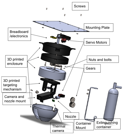
A ceiling-mounted pod (≈10 ft coverage radius) reads the room with a thermal camera, drives a two-axis servo gimbal onto the hottest point above a fire threshold, and opens a solenoid valve to release a pressurized water mist once it's centered.
- Targeting logic centers the gimbal on the hottest pixel in the thermal frame once it crosses 50°C, then holds and fires.
- Live telemetry — temperature, fluid level, battery — streams over BLE to a companion app.
- The mechanical arm and nozzle went through three design generations across 87 CAD files before the final geometry; formal engineering test procedures target extinguishing a contained fire in under 5 seconds at ranges from 2 to 10 feet.
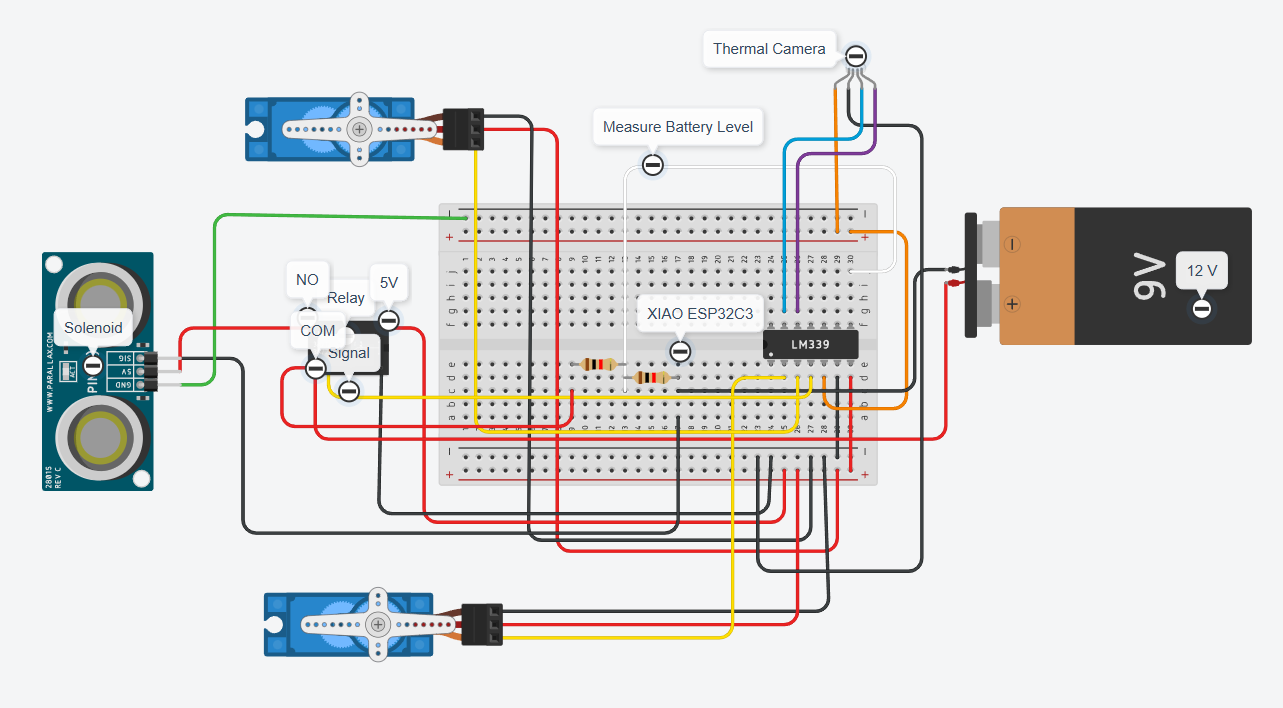
- A dedicated wiring diagram (Fig. 04) documents the full electronics build: dual servos, relay, solenoid, and battery-level sensing on an LM339 comparator.
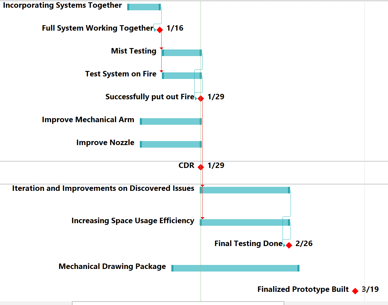
- Project log records the system successfully putting out a live test fire on 1/29 — the video above is that test — ahead of that day's Critical Design Review.
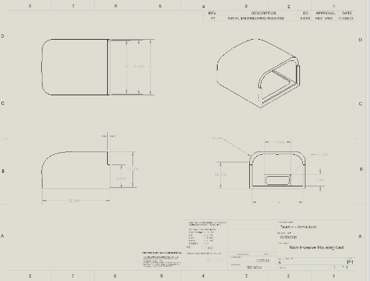
- Finalized prototype completed 3/19 after a pass on space efficiency and a full mechanical drawing package.
- Full bill of materials came to $334.05 across 26 line items; a fabrication guide and safety/operation manual were written for repeatable builds.
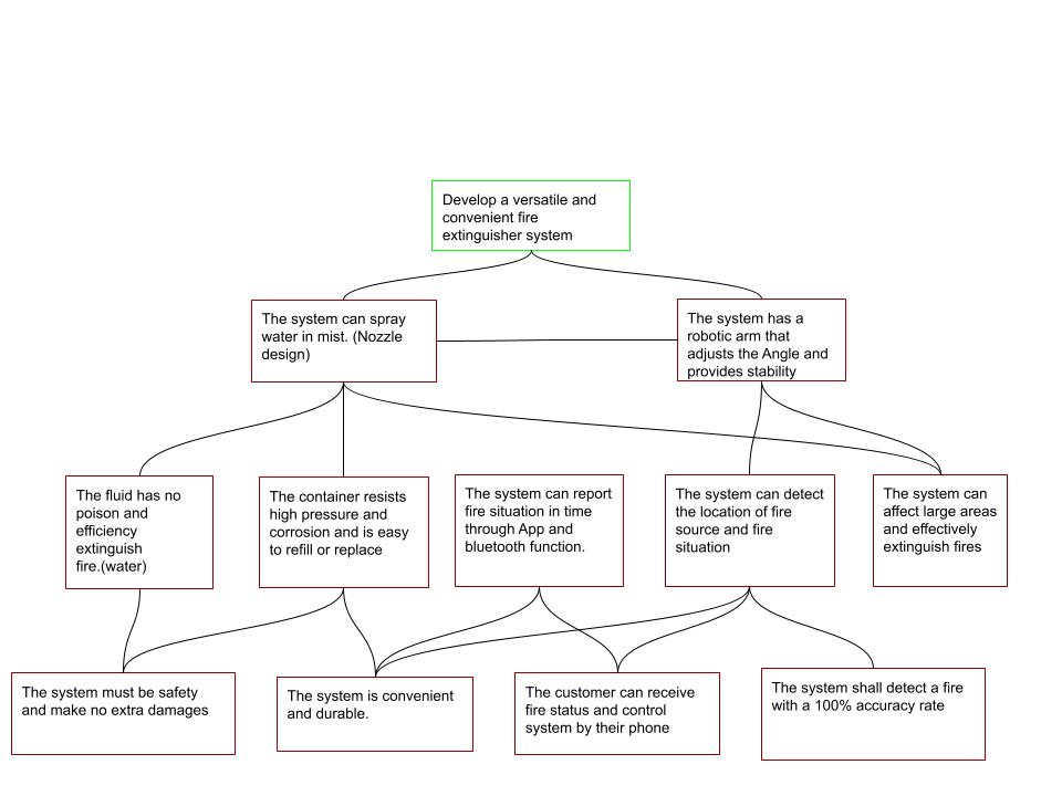
- Pitched under their own brand, Fire-Fight Club, with the funding case resting on three points: inexpensive and easy to install, autonomous rather than manually triggered, and app-monitored end to end.


SmartSweat — Wearable Lactate Biosensor
The electronics worked. The chemistry didn't survive shipping — here's why.
TeamTeam SmartSweat — Agustin Gutierrez, Luke Hsing, Tanya Nguyen, Eileen Hom
Academic year2025–2026
Officialprojects.eng.uci.edu ↗
Coaches want a read on an athlete's exertion in real time, but the standard method means drawing blood and running it through a lab analyzer. The sponsor asked for a non-invasive alternative: a patch that reads lactate straight from sweat.
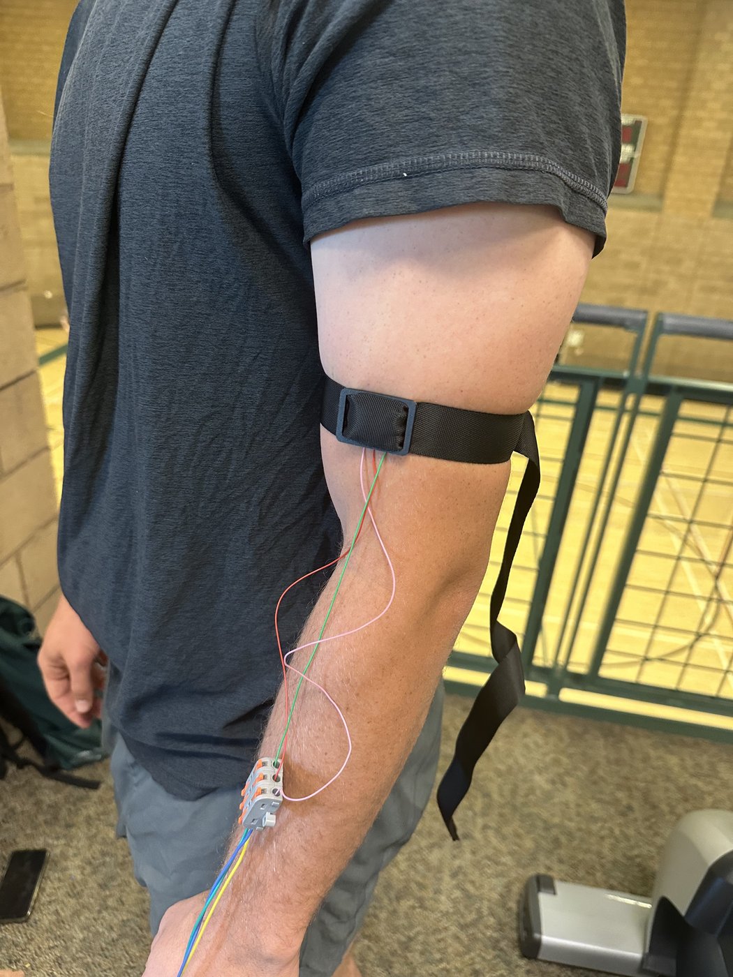
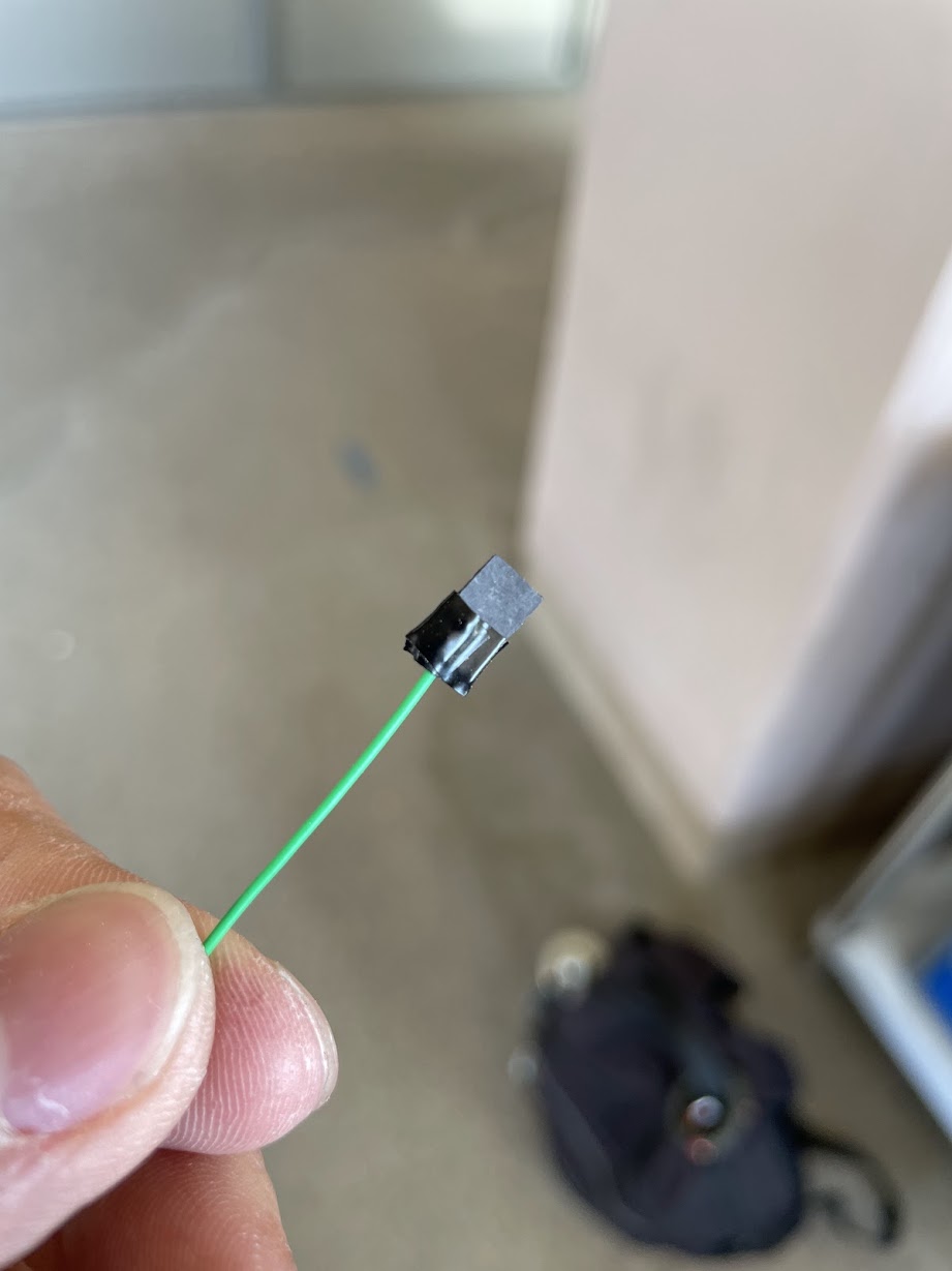
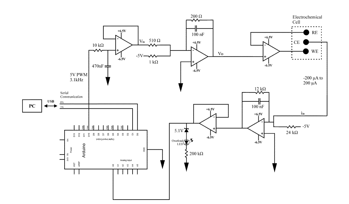
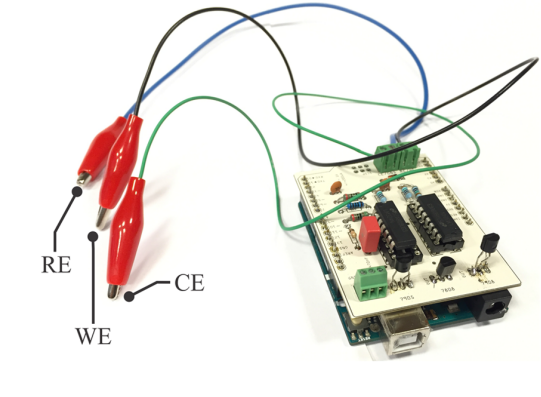
A wearable patch worn against the skin measures lactate in sweat through a custom potentiostat and an enzyme-functionalized membrane — built and calibrated from the electronics up, on an 18-week timeline compressed to about 10 working weeks after a delayed project approval.
- The potentiostat was validated against known hydrogen-peroxide concentrations first, bypassing the enzyme layer to confirm the electronics before trusting the chemistry.
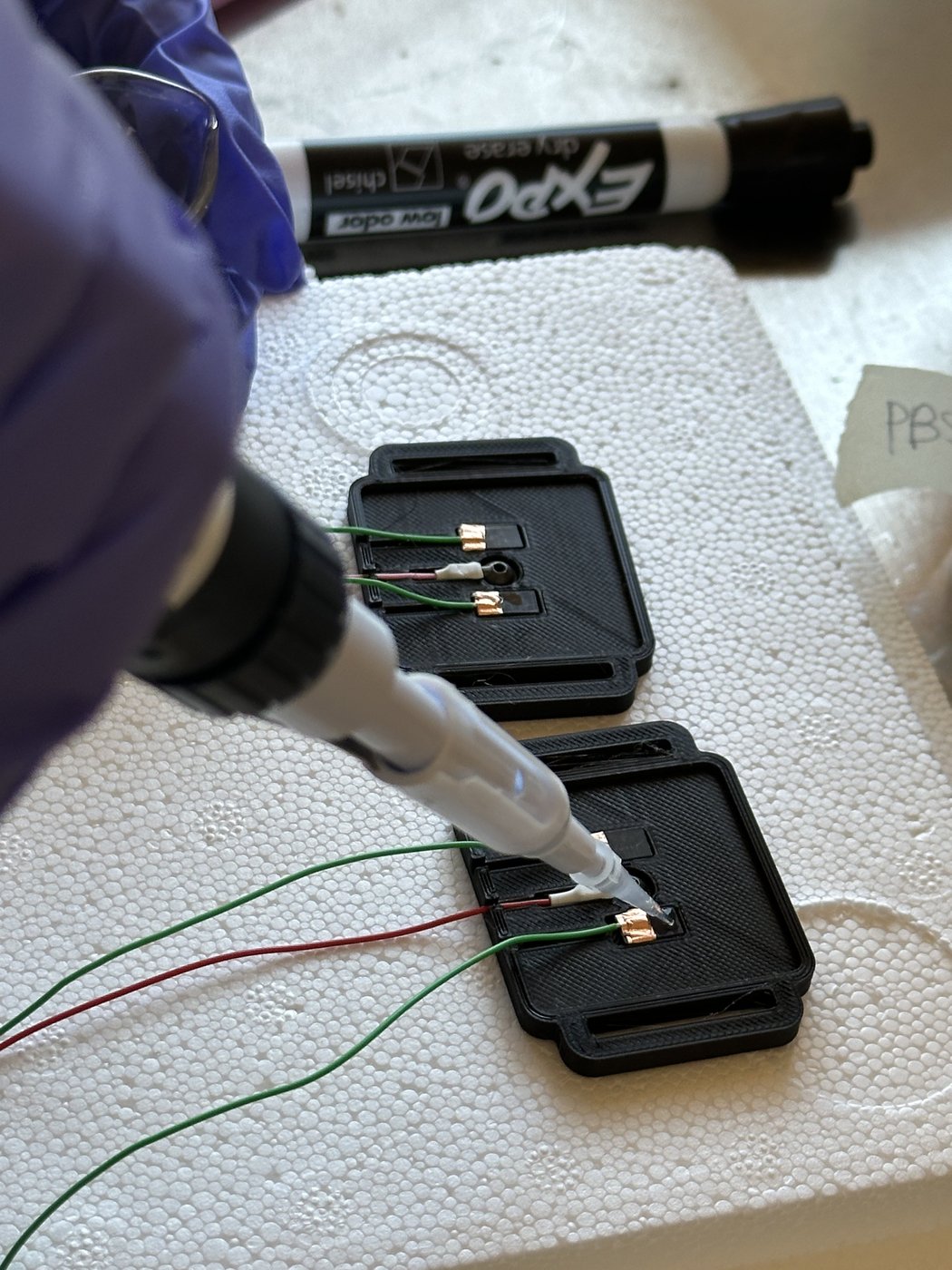
- The enzyme membrane is hand-manufactured over a multi-day chemical process, cast onto graphite electrodes and air-dried.
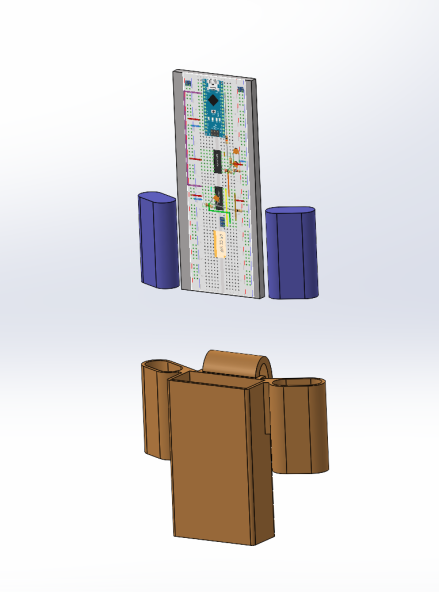
- Housing iterated through a watchband-integrated capsule and a compact waistband module, wear-tested for stability, fit, and comfort.
- Requirements traceability was tracked line-by-line against pass/fail criteria — the team's own discipline is what surfaces the honest result below.
- The research phase weighed alternatives before committing to lactate — body-odor profiling and cortisol sensing were both evaluated and set aside in favor of a sweat-lactate approach.
- Electronics and mechanical subsystems passed verification outright: stable output over a full hour of simulated exercise use, independent battery operation, and a housing that stayed put and stayed comfortable through wear-testing.
- The lactate-sensing chemistry did not survive the supply chain: the enzyme sat at room temperature for 3 days in university purchasing before the team could refrigerate it, most likely denaturing it and leaving the electrode layer unable to selectively detect lactate — 3 of 4 chemistry requirements are logged as failed in the team's own traceability matrix.
- Root cause, cost, and schedule impact were all documented rather than glossed over: BOM landed at $632 against a $400 budget (a same-part replacement enzyme alone would have added $216 and another week of lead time), which the team's own retro ties directly to the compressed timeline.
- Benchmarked against every commercial lactate sensor on the market (Onasport, Pinnacle, Zimmerman Peacock, and others) to confirm the price/performance gap this device is meant to fill, and pitched for continued funding on that basis — the enzyme fix is the next item in the pipeline, not a dead end.
EBBO+ E-Bike Battery Pack
Cooling airflow for a battery pack, proven with a thermometer, not just a simulation.
TeamTeam 13 — Christine Joy Angeles (Lead), Wen Wu (Product Design), Andrew Liu (QA), Wen-Kai Kevin Lee (Manufacturing) — advised by Mark Walter and David Copp, with UCI's Battery Lab
Academic year2023–2024
Officialprojects.eng.uci.edu ↗
E-bike packs cram dense lithium-ion cells into small enclosures with little airflow — a known thermal-runaway risk. The sponsor's brief was ambitious on purpose: something genuinely new in the category, not an incremental tweak, with a hard thermal ceiling of 40°C.
A redesigned 14s3p (42-cell) enclosure pairs a battery management system with active cooling airflow, sized and verified in CFD before a single part was cut — then proven again with a thermocouple against a fan-off control.
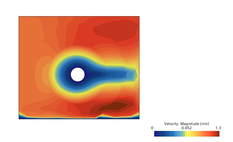
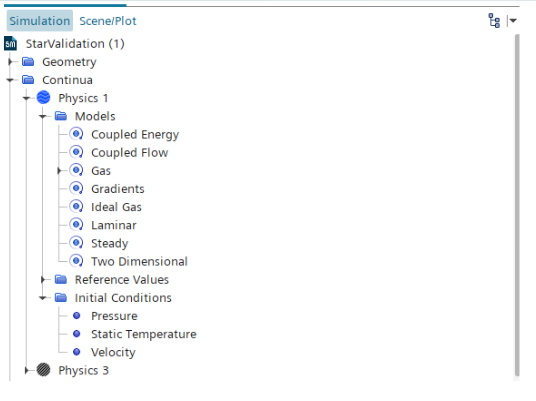
- Airflow and fan placement were validated in Siemens StarCCM+ CFD before committing to a physical build.
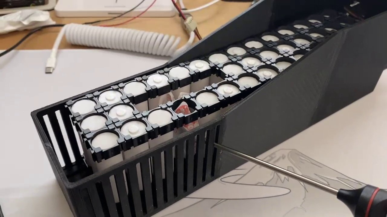
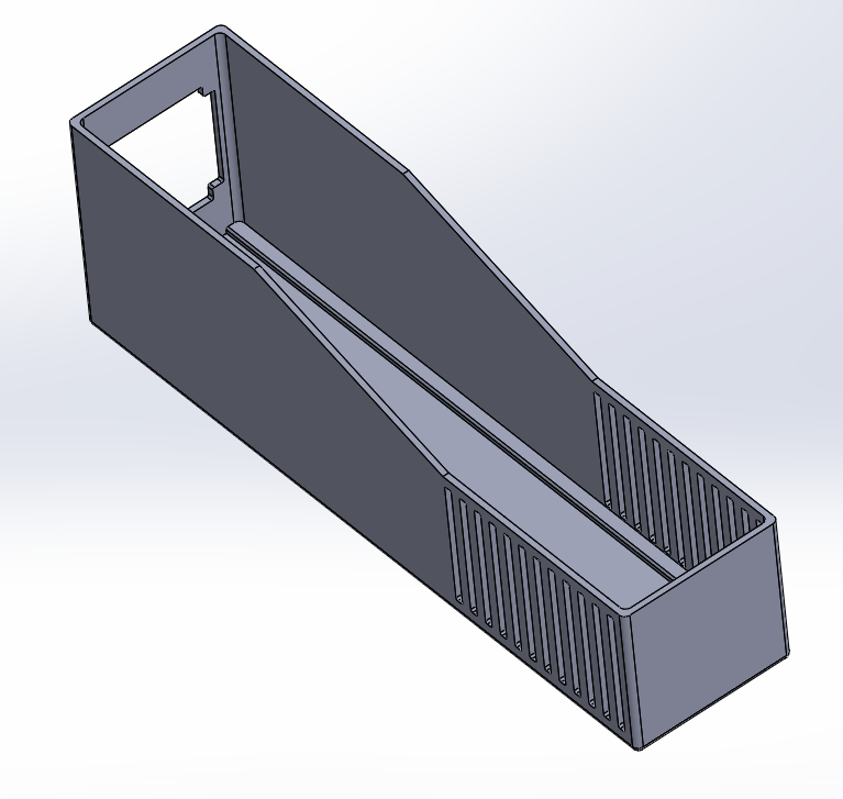
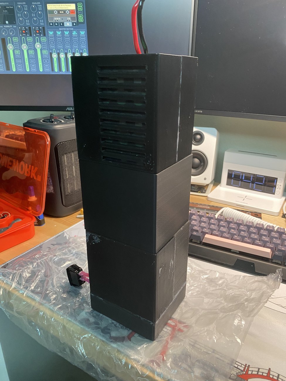
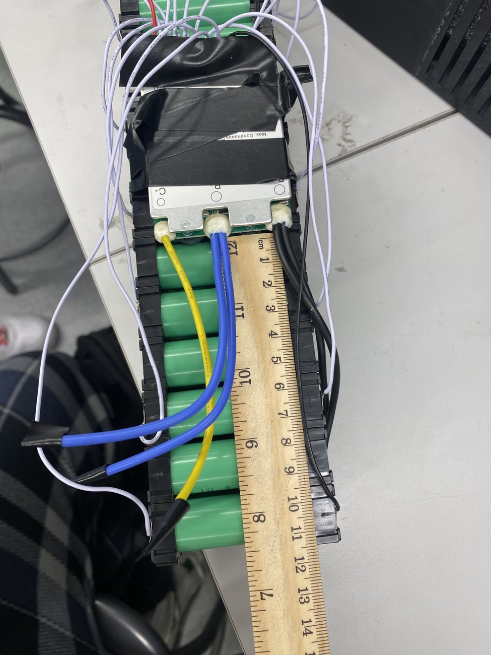
- A custom cell holder carries the 14s3p pack alongside the BMS and a DC-DC converter for auxiliary power, inside an enclosure that iterated through three generations — Prototype C integrates cell holder, BMS, and fan cooling path into one case, lid, and fan-lid assembly.
- Safety envelope was set explicitly before testing began: 60A discharge ceiling, per-cell voltage window of 2.5–4.25V, and a hard 40°C thermal limit.
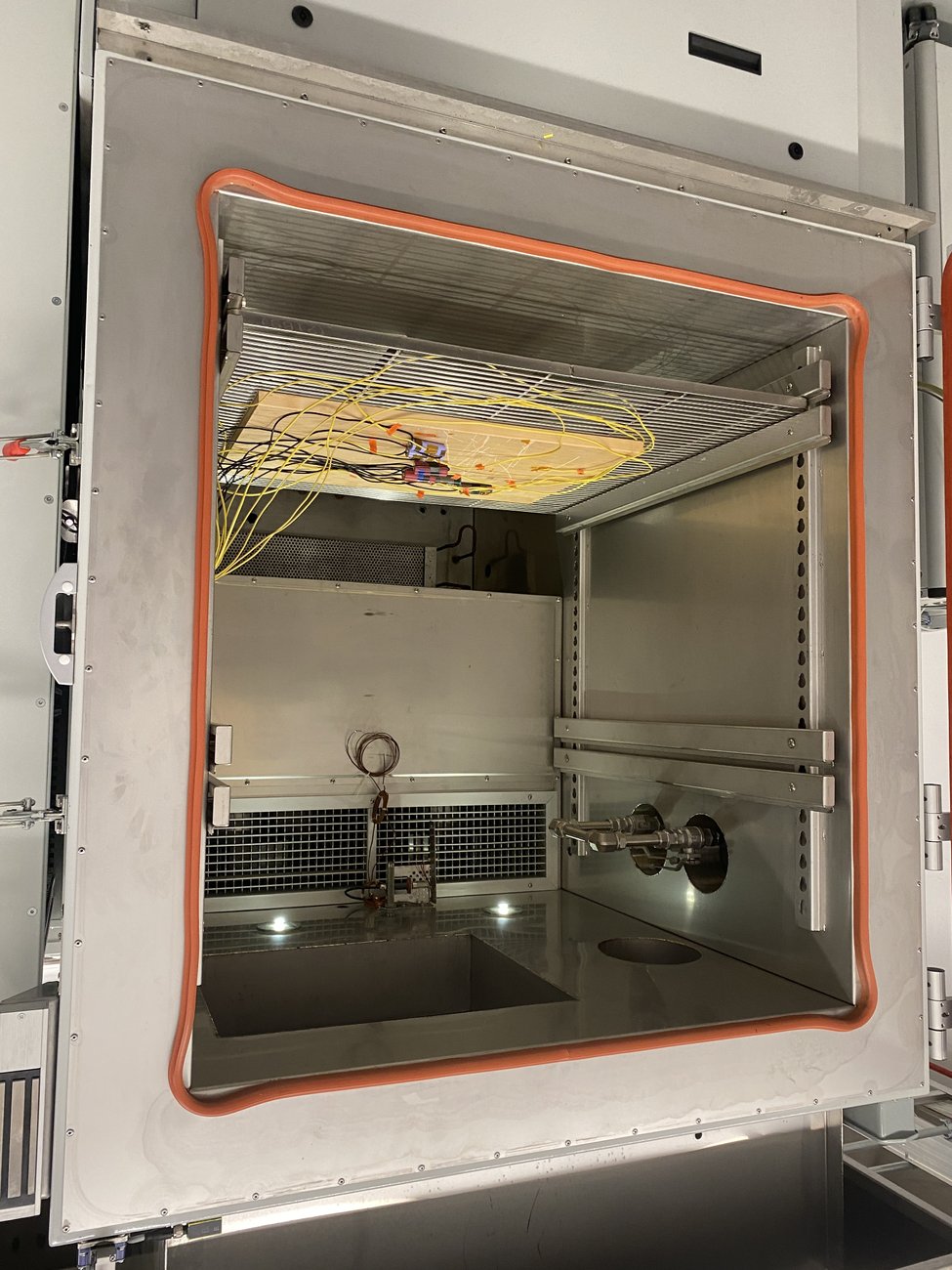
- Validated in a real environmental test chamber, not just on a bench — the full pack was instrumented with thermocouples and run inside a controlled-temperature enclosure (Fig. 03).
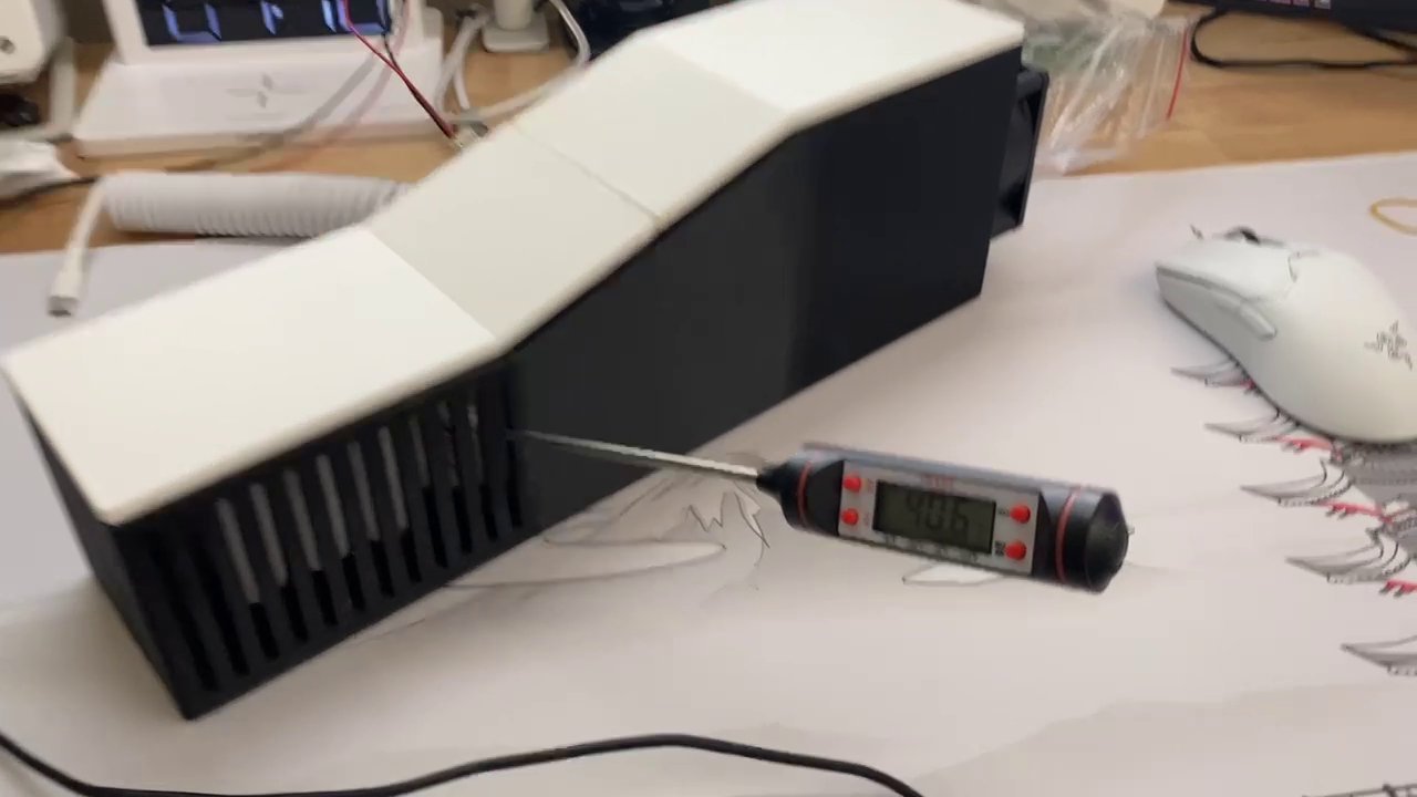
- Side-by-side proof-of-concept testing (see the chart below, and Clip 01 for the physical test) is the real evidence: with the fan off, pack temperature held flat near 50°C for 40+ minutes with no meaningful drop. With the fan on, temperature fell at an average of −0.39°C/min across trials — as fast as −0.48°C/min — pulling the pack down into the mid-30s°C, comfortably inside the 40°C ceiling.
- One trial turned the fan off partway through and watched the pack start reheating immediately — the clearest possible confirmation that the cooling path, not ambient drift, is what's doing the work.
- Delivered as a two-quarter (151A + 151B) capstone, with sponsor interviews, a pitch deck, and a poster presentation — pitched for continued funding to carry the pack past this prototype stage.
Simulating Before Cutting Metal
CFD and thermal simulation work behind the EBBO+ battery pack — run in Siemens StarCCM+ and Ansys before a single part was fabricated.
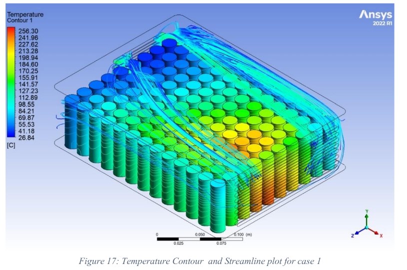
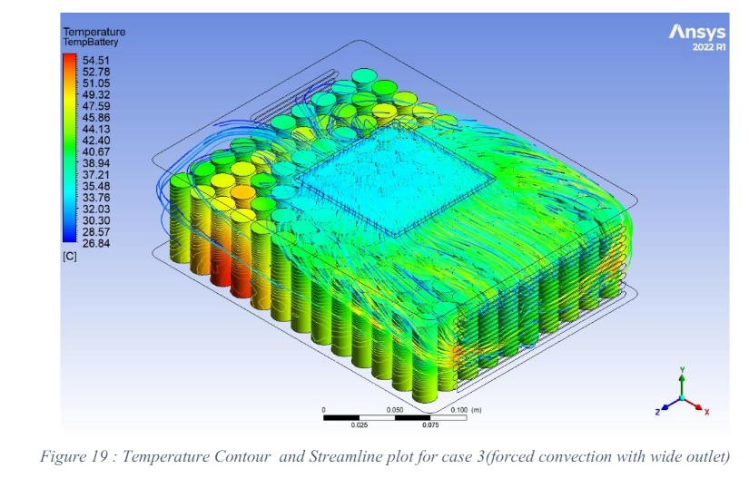
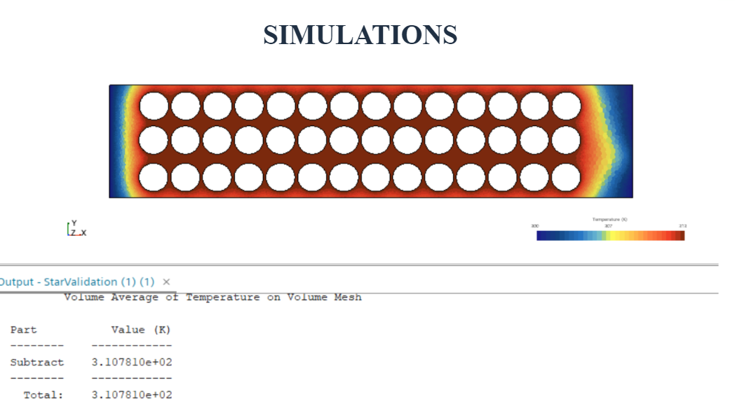
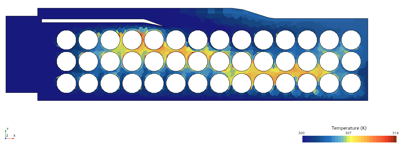
Before committing to an enclosure, the team modeled how heat actually moves through a 42-cell pack — with and without airflow. The spread between cases is the whole argument for active cooling: a sealed, natural-convection pack cooks itself past 200°C at the hotspot, while the same geometry with a fan-fed duct holds every cell under 55°C.
Ansys gave a full 3D temperature-and-streamline picture of airflow moving around individual cells (Sim. A/B); Siemens StarCCM+ was used for faster 2D cross-section sweeps to compare duct geometries before settling on the final case design (Sim. C/D). Both point the same direction, which is part of why the physical thermometer test later confirmed the same effect.
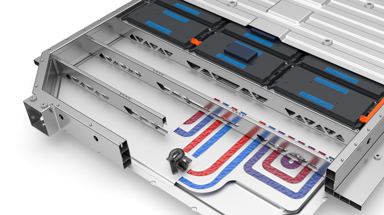
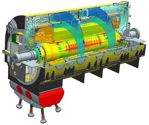
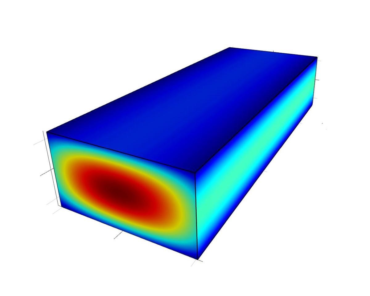
I also work with these tools professionally — through Saratech, a Siemens Simcenter partner. The four examples below are not from a UCI project or Saratech's own work; they're Siemens' own vendor case studies and product-capability material, included here (with credit) to show the professional-grade version of the same fluids/thermal problem the EBBO+ team tackled as students — a battery pack's cooling design carried all the way from molecular electrolyte chemistry up to full production hardware, and the same category of problem showing up again at gas-turbine scale.